
RS-485 roles
Verified on Edge Server release 5.4.0.
A Controller has one RS-485 port. The port has one role at a time.
| Role | The Controller | Use it for |
|---|---|---|
| Modbus Slave | Answers a Modbus master. | An Edge Server over an RS-485-to-Ethernet adapter, Home Assistant, a building system or a PLC. |
| Modbus Master | Polls the Modbus devices on the bus. | Sensors and relay boards from the device library. |
| BACnet MS/TP | Is a BACnet device on an MS/TP trunk. | A BACnet building system. |
| USB App | Keeps the port for the desktop app. | A direct link through a USB-to-RS-485 adapter. |
Defaults
A new Controller is in the Modbus Slave role. A factory reset sets it back to Modbus Slave.
| Setting | Default |
|---|---|
| Role | Modbus Slave |
| Controller address | 1 |
| Line format | 9600 baud, 8 data bits, no parity, 1 stop bit (9600 8N1) |
| Outputs | Not commissioned. Each output refuses commands until you commission it. |
| Leak detection | Off |
A Controller that has never had a role set changes to BACnet MS/TP when a BACnet master speaks on the bus. See Auto-detection under BACnet MS/TP below.
Wire the port
The RS-485 port is connector J14: an M12 A-coded 5-contact receptacle. The contacts follow the CANopen and DeviceNet assignment.
| Contact | Cordset colour | Signal | Notes |
|---|---|---|---|
| 1 | Brown | Not connected | Do not connect a shield drain here. |
| 2 | White | V_OUT | Switched 12 V, 0.75 A hold, 1.5 A trip. |
| 3 | Blue | GND | Bus and power return. |
| 4 | Black | RS-485 A | Line A. |
| 5 | Grey | RS-485 B | Line B. |
- Use two-wire half-duplex RS-485. On a half-duplex bus, only one device can send at a time.
- Connect A to A and B to B. Some vendors swap the A and B names. Check the device manual.
- Connect a common ground (contact 3) where the device needs a reference.
- Terminate the bus at its two ends only.
- Connect the cable shield at one end only, away from the Controller.
- Do not use V_OUT to power a device that has its own supply.
The bus has no password. Any device on the bus can read and control the Controller. Protect access to the bus and to any network adapter on it.
Every device on one bus uses the same baud, parity and stop bits. A repeater does not let you mix them. Give each device its own address, 1 to 247.
Change the role
The steps are the same in the web app and the desktop app.
- Select Control in the sidebar.
- Select the Controller.
- Open Controller settings, then the Fieldbus tab.
- Under RS-485 port, select the role.
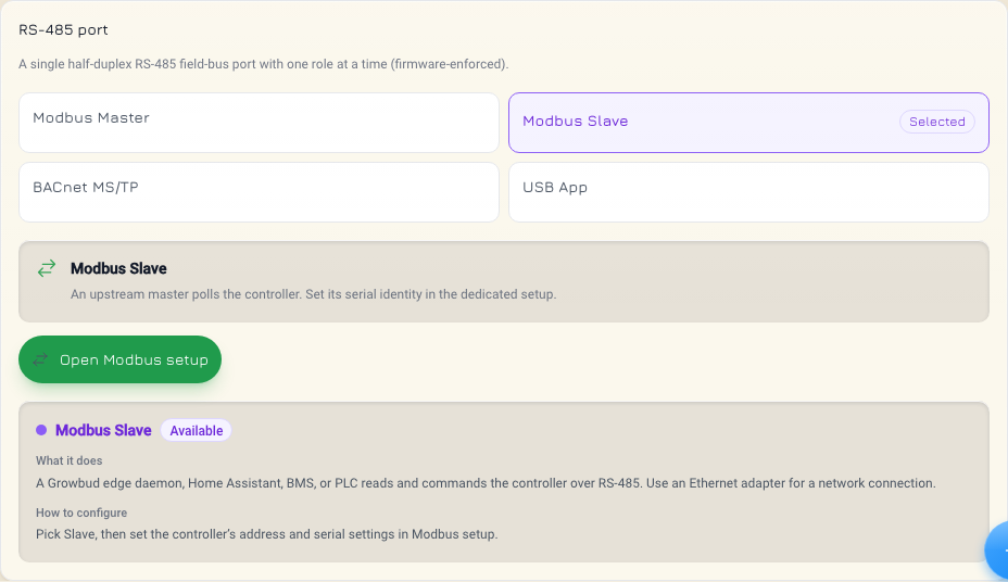
The Wireless tab can also take the port. When the backhaul is Ethernet / RS-485, the port is in the Modbus Slave role, and the Fieldbus result shows Used by the backhaul. You cannot add Modbus devices or use BACnet on the port while it carries the backhaul.
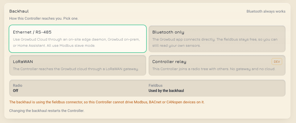
A role change stops the work of the old role:
- To Modbus Slave or BACnet MS/TP: the Controller stops polling. It keeps the master configuration. When you go back to Modbus Master, polling starts again with no new configuration.
- To Modbus Master or BACnet MS/TP: the Controller stops answering a Modbus master.
- A role change cancels queued bus work.
If a role change fails, the Controller stays on its old role. If it fails again, remove power from the Controller, then apply power again. A restart from the app does not help. If a role cannot start at boot, the Controller goes back to Modbus Slave.
Modbus Slave
In the Modbus Slave role, the Controller works with no app, no account and no gateway. The master reads and controls it through the register map.
- Function codes:
0x03read holding,0x04read input,0x06write single,0x10write multiple. Other codes answerILLEGAL_FUNCTION. - Registers are 16-bit, big-endian on the wire, addressed from 0.
- Broadcast (address 0) is not supported. The Controller ignores it.
- Reserved registers read as 0. A write to a reserved register answers
ILLEGAL_DATA_ADDRESS.
Set the address and line format
Set the Controller address in the app:
- On the Fieldbus tab, select Modbus Slave.
- Select Open Modbus setup.
- Select Edit configuration.
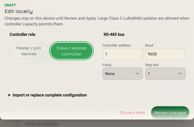
- Under Controller role, select Slave / expose controller.
- Under RS-485 bus, set Controller address, Baud, Parity and Stop bits.
- Select Review changes.
- Select Confirm and apply.
A master can also set the address and the role:
| Holding register | Name | Values |
|---|---|---|
0x0000 | Controller address | 1 to 247. Other values answer ILLEGAL_DATA_VALUE. |
0x0001 | Role | 0 Modbus Master, 1 Modbus Slave. BACnet MS/TP cannot be set here. |
The Controller saves the change before it applies it. A write to 0x0001 also turns off BACnet auto-detection.
A write of 0 to
0x0001ends the slave session. The Controller becomes a master and stops answering your requests.
Register blocks
| Block | Registers | What |
|---|---|---|
| Global | 0x0000-0x000F | Device status, leak, sensor input, comms loss. Holding: address, role, leak detection, input setup. |
| Per channel | 0x0010-0x004F | 16 registers for each output. Channel n starts at 0x0010 + n × 0x10. |
| Schedules | 0x0050-0x005F | Schedule staging. |
| Linked sensors | 0x0060-0x00DF | Samples from linked sensors. Input table only. |
| Device | 0x00E0-0x00EF | Identity, clock and standalone settings. |
Addresses at 0x0440 and above answer ILLEGAL_DATA_ADDRESS.
Per-channel registers
Each output has a 16-register block. Add the offset to 0x0010 + n × 0x10, where n is the channel, 0 to 3.
Some terms in these tables:
- A held output stays on with continuous DC drive until a command turns it off.
- A DC pulse valve is a latching valve. A short pulse moves it, and it then stays in place with no power. Continuous DC drive can burn it.
- The latch stroke is the length of the pulse that moves a DC pulse valve.
Holding registers (0x03, 0x06, 0x10):
| Offset | Name | What |
|---|---|---|
| +0 | On/off | 0 off, any other value on. |
| +1 | Level | 0 to 100 percent. |
| +2 | Pulse | Bits 0-14: duration in ms. Bit 15: 0 open, 1 close. |
| +3 | Device type | 0 unconfigured, 1 DC pulse valve, 2 solenoid valve, 3 relay, 4 pump, 5 fan, 6 light. Bit 15 acknowledges continuous DC drive. |
| +4 | Latch stroke | 10 ms units. 0, or 5 to 100. DC pulse valve only. |
| +5 | Input kind | 0 voltage, 1 4-20 mA, 2 pulse, 0xFFFF nothing fitted. |
| +6 | Continuous DC allowed | 1 allows a held output, 0 forbids it. |
A read of +0 to +2 gives the last command that the Controller applied, not the live state.
Input registers (0x04):
| Offset | Name | What |
|---|---|---|
| +0 | State | Live output state. |
| +1 | Fault | Channel fault. |
| +2 | Level | 0 to 100 percent. |
| +3 | Current | mA. |
| +4 | Device type | As commissioned. 0 refuses every command. |
| +5 | Input kind | 0 voltage, 1 4-20 mA, 2 pulse, 0xFFFF nothing fitted. |
| +6 | Input mV | Voltage and 4-20 mA kinds. |
| +7, +8 | Pulse count | Low word, high word. Free-running. Take differences. |
| +9 | Input valid | 1 when the last sample succeeded. |
| +10 | Capability | Bit 0 on/off, bit 1 pulse, bit 2 level. |
| +11 | Latch stroke | 10 ms units. 0 is the firmware default. |
| +12 | Continuous DC allowed | 1 when a held output is allowed. |
| +13 | Hold owner | 0 none, 1 on-device hold armed, 2 hold running. |
Commission an output before you command it. Write the device type to offset +3. When the outputs switch DC, every type except the DC pulse valve needs bit 15 set, unless offset +6 already reads 1.
Device block (0x00E0-0x00EF)
| Offset | Input register | Holding register |
|---|---|---|
| +0, +1 | Serial, low word and high word | Reserved |
| +2 | Hardware revision | Reserved |
| +3 | Clock, low word | Clock, low word. This write applies the time. |
| +4 | Clock, high word | Clock, high word. Write it first. |
| +5 | Clock valid, 0 or 1 | Reserved |
| +6 | Comms-loss timeout, minutes | Comms-loss timeout, minutes |
| +7 | Schedules stored | Reserved |
| +8 | Channels on this device | Reserved |
| +9 | Protocol version | Reserved |
| +10 | Capability flags | Reserved |
| +11 | Factory product type | Reserved |
| +12 | Identity magic 0x4743 ("GC") | Reserved |
| +13 | Continuous DC drive acknowledged, 0 or 1 | Reserved |
To set the clock, write UNIX time in seconds, UTC:
- Write the high word to
0x00E4with function0x06. - Write the low word to
0x00E3with function0x06.
Do not write both words in one 0x10 request. The Controller refuses it, because the low word lands first. The Controller also refuses a time before 2020. Schedules do not run until the clock is set.
When the protocol version is 1 or more, check that the identity magic is 0x4743.
Exceptions
| Exception | Code | When |
|---|---|---|
ILLEGAL_FUNCTION | 0x01 | The function code is not supported, or the output cannot do the operation. |
ILLEGAL_DATA_ADDRESS | 0x02 | The register is outside the map, or the write is to a reserved register. |
ILLEGAL_DATA_VALUE | 0x03 | A count or value is out of range. |
SLAVE_DEVICE_FAILURE | 0x04 | An interlock refused the command: leak, harness, fault, unconfigured output or break-before-make. |
An interlock is a safety rule that blocks a command. Break-before-make is the interlock that turns one output off before a paired output turns on. SLAVE_DEVICE_FAILURE is an interlock at work, not a bus error.
An Edge Server on the slave port
An Edge Server reaches a Controller in the Modbus Slave role through an RS-485-to-Ethernet adapter on the site network. Over this wired link, the Edge Server reads the Controller and switches its outputs. A command sent this way shows transport rs485 in the API.
Use one master on the bus. Do not connect an Edge Server and Home Assistant as two masters on one bus.
With Home Assistant as the master, the Controller stays a slave. Home Assistant then polls the library devices on the same bus itself, each at its own address. Every device must use the Controller's line format.
Modbus Master
In the Modbus Master role, the Controller polls the devices on the bus and keeps the readings. The Controller polls the devices without the Edge Server. The Edge Server stores the configuration, sends changes over LoRaWAN and publishes the readings.
- On the Fieldbus tab, select Modbus Master.
- Select Open Modbus setup.
- Select Edit configuration.
- Under Controller role, select Master / poll devices.
- Under RS-485 bus, set Baud, Parity and Stop bits for the whole bus.
- Add the devices.
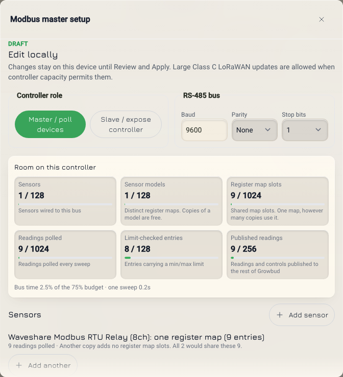
The Configure Modbus devices guide gives every step.
What the master role changes:
- The Controller no longer answers a Modbus master.
- A Modbus point write needs this role. In another role, the write answers
422withreasonMODBUS_MASTER_MODE_REQUIRED. - A Modbus point write goes over LoRaWAN only. The wired link cannot carry it.
- The Controller retries a read that times out or fails its CRC check. It does not retry a Modbus exception.
If a device ships with a different line format, change the device first. For example, an Apogee quantum sensor ships at 19200 8E1.
BACnet MS/TP
The Controller can be a BACnet MS/TP device on the RS-485 port. An MS/TP trunk is the bus that connects the BACnet devices.
Auto-detection
A Controller that has never had a role set listens for BACnet. Every MS/TP frame starts with 0x55 0xFF. A Modbus request never starts with these bytes. After two such preambles from a BACnet master, the Controller changes to BACnet MS/TP and keeps that role after a restart.
When you set a role, in the app or at holding register 0x0001, the Controller stops this detection for good.
Set up BACnet MS/TP
- On the Fieldbus tab, select BACnet MS/TP.
- Turn on Enable BACnet. It is off by default. When it is off, the Controller publishes no points.
- Under Connection, select MS/TP (RS-485).
- Set Device Instance, 0 to 4194303. It must be unique on your BACnet network.
- Set MAC address (0–127), Baud and Max master (1–127). Use the values of your MS/TP trunk.
- Select the points to publish.
- To let the building system control outputs, turn on Allow BMS writes to outputs.
Max master is the highest MAC address of a BACnet master on the trunk. The Controller looks for other masters up to this address only.
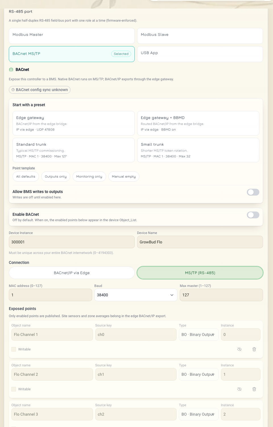
The app offers 9600, 19200, 38400 and 76800 baud. The Controller applies the role and the settings when it next receives its configuration from the app.
With no point list, the Controller uses device instance 300001 and MAC address 1. It publishes this default list of 32 objects:
| Object | Instances | What |
|---|---|---|
| Binary Output | 0-3 | Outputs 1-4, commandable |
| Analog Output | 0-3 | Output level in percent, commandable |
| Analog Input | 0-3 | Output current |
| Binary Input | 20, 21 | Leak detected, comms loss |
| Binary Input | 22 | Clock set |
| Binary Input | 23, 24 | LEAK 1 wet, LEAK 2 wet |
| Binary Value | 0-3 | Output 1-4 continuous DC allowed, writable |
| Binary Value | 30 | Leak detection on or off, writable |
| Analog Value | 31 | Sensor input kind and port, writable |
| Analog Value | 32 | Comms-loss timeout in minutes, writable |
| Analog Value | 33, 34 | Clock high word, low word, writable. Write 33 first. |
| Analog Input | 10 | Sensor input mV |
| Analog Input | 12 | Board temperature |
| Analog Input | 40-43 | Input 1-4 mV (voltage and 4-20 mA kinds) |
A configured point list replaces the default list. The Controller keeps the BACnet settings through a restart and a power loss (firmware 5.3.0 or newer). A factory reset clears them.
USB App
The USB App role keeps the port for the desktop app. The desktop app connects through a USB-to-RS-485 adapter from the Controller's Control page. Disconnect the adapter before you set the port back to Modbus or BACnet.
Read and set the Modbus mode through the API
These routes need Edge Server 5.4.2 or later. They are standard routes and need no setting. The app uses other routes, so the steps above work on every Edge Server.
The API calls the role mode. The mode is the Modbus mode that you want: slave or master. It does not show BACnet MS/TP or USB App. A Controller in the BACnet MS/TP or USB App role still shows its last Modbus mode.
GET /sensing/v1/controllers/{serial}/modbus/config returns { "config": { ... } }:
config.config.modeisslaveormaster.config.config.busholdsslave_address,baud,parityandstop_bits.config.etagandconfig.desired_versionidentify this version. Keep them for the change.
A Controller with no configuration returns the default: mode slave, address 1, 9600 baud, no parity, 1 stop bit.
An organization admin can change the mode with PATCH /control/v1/controllers/{serial}/modbus/config and the operation {"op": "set_mode", "mode": "master"}. Send the etag in the If-Match header. Send desired_version as base_desired_version. BACnet MS/TP and USB App are not set through this route.
SERIAL=<serial>
ETAG=<config.etag from the GET>
VERSION=<config.desired_version from the GET>
curl -sk -X PATCH \
  -H "Authorization: Bearer $TOKEN" \
  -H 'Content-Type: application/json' \
  -H "If-Match: \"$ETAG\"" \
  -d '{"base_desired_version": '"$VERSION"', "operations": [{"op": "set_mode", "mode": "master"}]}' \
  "https://<your Edge Server address>:8443/control/v1/controllers/$SERIAL/modbus/config?wait=30"
The mode change is an operation. The Edge Server sends it to the Controller over LoRaWAN, and this can take minutes. A 202 answer means the operation is still running. Follow poll until operation.status is applied. The port changes only then.
The Controllers reference lists the answers and errors.