
Controller
Current lead time: 6 weeks
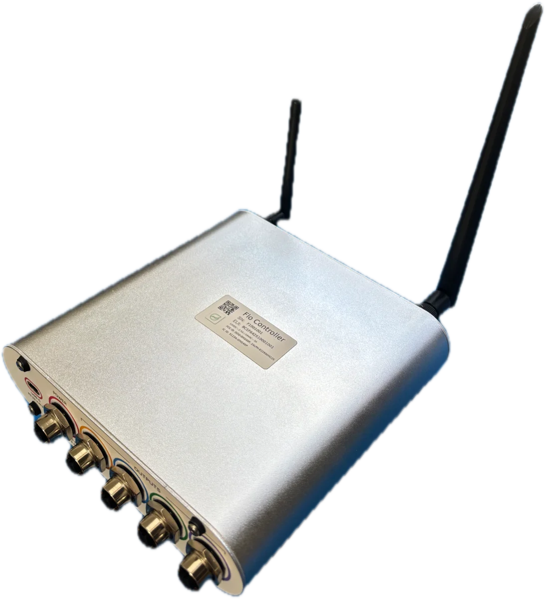
Price
Works with the free app over Bluetooth, with or without a gateway.
Overview
Control
Communication
Sensing
Power
Power supplyincluded, plugs straight into the controller
Assembled in the USA
Made by the people who support it
Dro, Vero, and the Controller are assembled in the United States. This one ships in about 6 weeks, and placing an order reserves your units from the next production run.
- Pay now and we email tracking the day it ships, or reserve your units without paying and settle when it leaves. Your choice.
- The 90-day return window starts when your order arrives, not when you place it.
- Free US and Canada shipping on orders of $200 or more.
If you have a deadline or an install date to hit, tell us about it and we will give you a straight answer on timing.
Product Details
Works with Growbud App Platform
Free Professional-Grade Monitoring and Analytics
Real-Time Monitoring
- Live sensor data streaming with sub-second updates
- Customizable alerts and notifications
- Historical data tracking and trend analysis
Advanced Analytics
- AI-powered insights and recommendations
- Multi-sensor comparison and correlation
- Export data for research and reporting
Download the free Growbud app to unlock the full potential of your Controller


Technical Specifications
Valve Zones
4 Channels
Four independent zones for standard 24 VAC solenoids or latching DC valves, chosen in configuration. All four zones can run at once: each AC channel drives up to 1.35 A, with a 2.2 A total across the controller, which four typical 0.2–0.4 A solenoids sit comfortably inside. Latching DC valves fire one at a time with a 3 A pulse. Every channel is protected by a self-resetting fuse
Sensor Inputs
4 Universal
Every valve port is also a sensor port: pulse, dry contact, or hall-effect flow, 4-20 mA, 0-10 V, or 0-3.3 V, each selected in firmware with switched 12 V excitation. Specify flow meters at or below roughly 500 pulses/litre
Leak Probes
2 Ports
Two identical two-electrode probe ports; either port takes either probe
RS-485 / CAN
Modbus + CANopen
One port, two buses: Modbus master for up to 128 wired sensors, Modbus slave or BACnet MS/TP for your BMS, or CANopen master/slave for actuators and industrial control. Switched, fused, current-monitored 12 V 0.75 A sensor power on the same cordset. Bring your own device: a large library of sensor and actuator profiles ships built in, and if yours is missing, email support@growbud.io with the model and we can usually add it in days
Without the app
Modbus or BACnet out of the box
Works on its own inside an existing system as a Modbus RTU device, and in common BACnet MS/TP configurations, with no Growbud app or cloud setup and reduced functionality. A factory reset from the button returns it to that state at any time
Home Assistant
Native integration
Every channel appears in Home Assistant as a native entity: valves, switches, lights, fans, and levels, plus the sensors linked to the Controller. No Growbud app, account, or cloud
BACnet
MS/TP + IP
Native building automation objects with priority arrays
Wireless
LoRaWAN + BLE
Miles of range on LoRaWAN; Bluetooth for phone setup
Circuit Protection
Auto-Reset Fuses
Self-resetting PTCs on every valve channel and on the supply input. An overload clears itself once the fault is removed, with no fuses to replace in the field
Power Input
USB-C PD / 12 VDC / 24 VAC
USB-C PD 5-20 V up to 20 W, 9-30 VDC nominal 12 V, or 20-26 VAC RMS nominal 24 V. The powered rail is detected at boot, fused and surge-protected
Scheduling
16 On-Board
Schedules run autonomously without a network connection
Deployment Scenarios
The Controller fits into your operation three ways: fully wireless alongside your Growbud sensors, hardwired into your building management system, or on your own LAN as a Home Assistant device. The RS-485 / CAN port does one job at a time: Modbus master to your industrial sensors, CAN master or slave to actuators and industrial control, or the building-system connection over Modbus slave or BACnet, with nearby Growbud sensors picked up over Bluetooth. Every configuration drives up to four valve zones, 24 VAC or latching DC, with one drive mode per unit, never mixed, and each of those four ports also reads a sensor. The valve counts below are just sample setups.
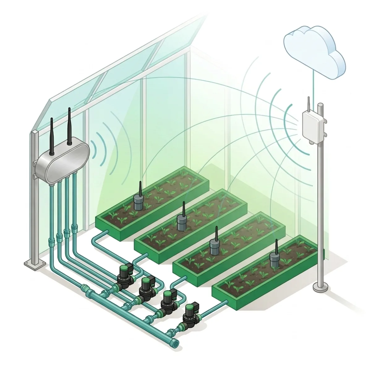
Wireless: LoRaWAN
Deploy the Controller exactly like your Dro and Vero sensors. Controller and sensors all join the same Growbud gateway. Shown here driving four 24 VAC valve zones on the irrigation manifold.
- • Controller + Dro/Vero sensors on one LoRaWAN network
- • Sample config: 4 AC valve zones on one 24 VAC supply
- • Wire RS-485 Modbus sensors (EC, pH, flow) straight in
- • Miles of range; scheduled actions run if the network drops
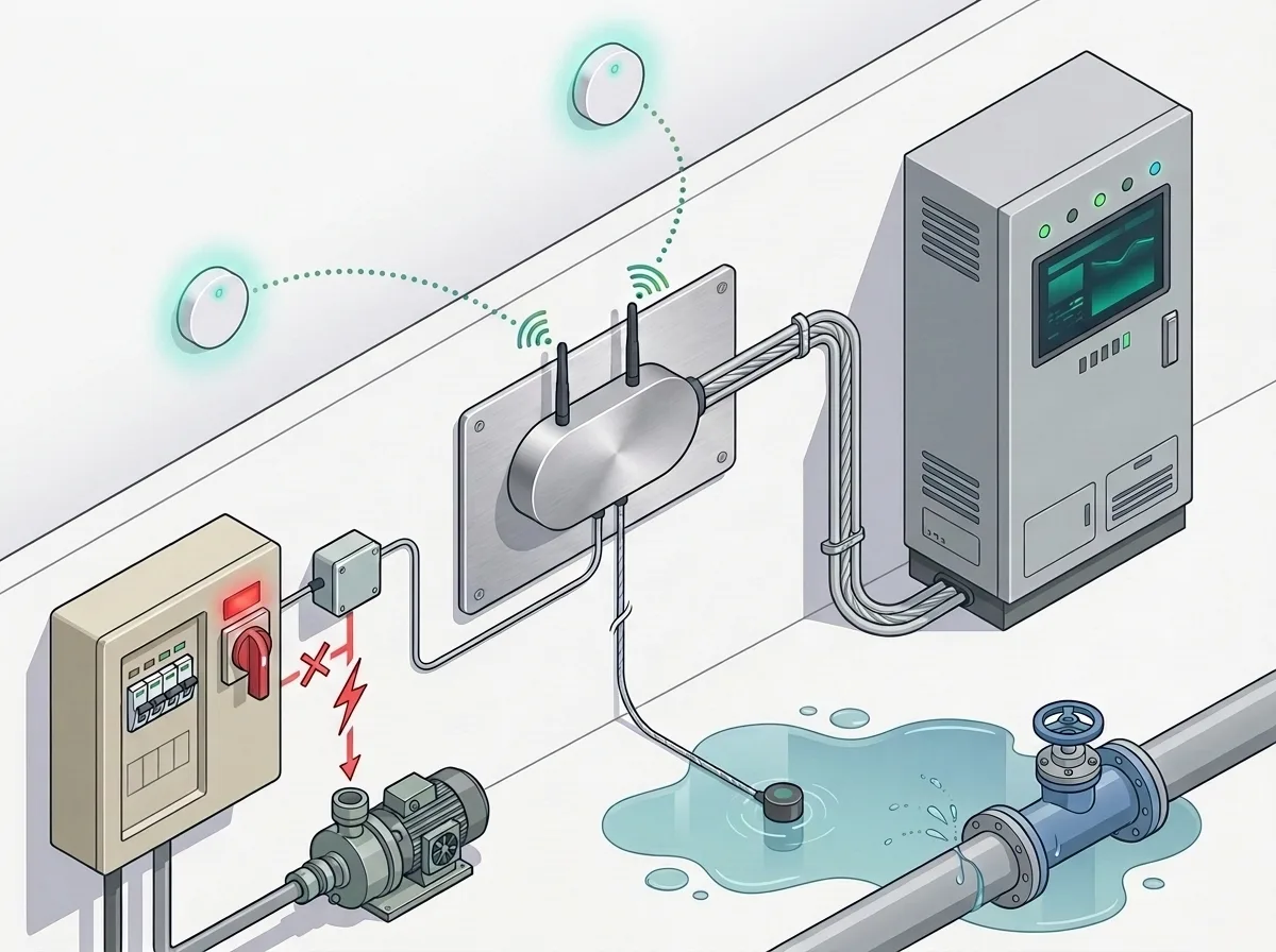
Building Automation: BACnet
Wire the field-bus port into your BMS as a BACnet MS/TP node. Two leak probes watch the floor, a dry-contact power relay stands ready to shut the pump down, and air-quality monitors report in alongside, all surfaced to the building system as BACnet objects.
- • BACnet MS/TP on RS-485 (BACnet/IP via gateway)
- • Two identical leak-probe ports; either takes either probe
- • Valve output drives a dry-contact relay for pump shutoff
- • Air quality, leak, and power control in one node
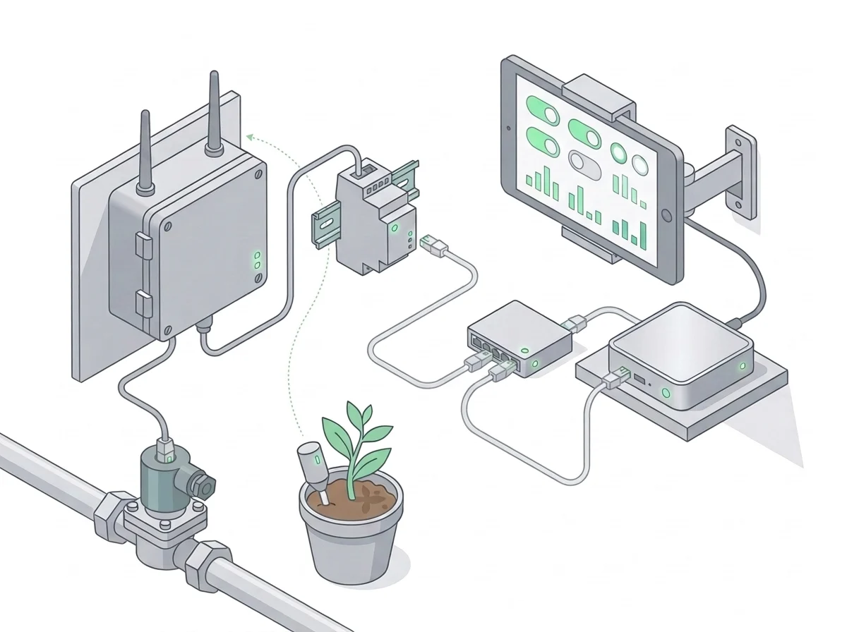
Your LAN: Home Assistant
Run the Controller from the Home Assistant you already have. An RS-485 to Ethernet adapter puts it on the same network as your Home Assistant box, and our integration turns every channel into a native entity you can automate.
- • Valve, switch, light, fan, and level entities with real state
- • Linked Growbud sensors come through with them
- • No Growbud app, account, or cloud at runtime
- • Button-press factory reset returns it to default Modbus
Valve drive
One controller, either kind of valve
24 VAC triac drive
20-26 VAC RMS · 1.35 A per channel
Polarity does not apply: the output is energised or it is not. Every channel is individually protected with self-resetting fuses, so doubling two or three small solenoids onto one output is fine. High-current zones simply run in sequence from the schedule.
Drive mode applies to all four outputs, so every valve on a controller is the same type: never mix 24 VAC and DC on one unit.
Connector Pinouts
Every port on the Controller uses standard M12 and M8 A-coded connectors. Tap a contact on the face view to see its signal, or use standard IEC-colour cordsets and match by conductor colour. Each of the four valve ports drives a valve and reads a sensor, and the two leak ports are interchangeable.
Power from one pair only: DC (1/2) or AC (3/4), never both.
M12 A-coded input · separate DC and floating AC pairs
Power input (J1)
| Pin | Wire | Signal | Function |
|---|---|---|---|
| 1 | Brown | VDC_IN | 9–30 VDC input |
| 2 | White | GND | DC return / circuit ground |
| 3 | Blue | VAC_HOT | 20–26 VAC RMS input; the HVAC R power leg |
| 4 | Black | VAC_RETURN | Floating AC return, the HVAC C common; not DC ground |
| 5 | Grey | NC | Not connected |
- IEC blue normally means 0 V. On the Power connector it does not: contact 3 is 24 VAC hot. Never treat the blue conductor here as a return.
- Coming from HVAC: contact 3 is the equivalent of the red R power wire and contact 4 is C, the common.
- Never bond contact 4 to contact 2 in the cable; the AC input is differential.
- Use either the DC pair (1/2) or the AC pair (3/4), not both supplies at once.
- Contact 5 is not connected. The grey conductor of a standard cordset is unused here.
Conductor colours follow IEC 60947-5-2 for standard A-coded cordsets. Terminate cable shields at one end only, away from the controller: no contact on any port grounds the shield at the controller end. Full wiring detail, register maps, and installation procedures are in the Controller manual.
Wiring
DC solenoid polarity
On a latching DC solenoid, valve contact A is positive and B is negative. On the M12 cable that is the brown conductor to A and the blue to B, so a typical solenoid wires red to brown, black to blue.
Getting it backwards will not damage the solenoid. It swaps which pulse opens the valve and which closes it, so the zone runs inverted and the Controller reports open while the valve is actually shut. If a zone behaves backwards, swap A and B.
In AC mode none of this applies. The output is simply energised or not, so A and B can go either way round. Only DC latching drive depends on wiring order for open versus closed.
Technical Documentation
Access comprehensive technical specifications, installation instructions, and usage guidelines for your Controller by downloading the product manual below.
Download Controller Manual (PDF)For additional support or questions about your product, please contact our technical support team.